
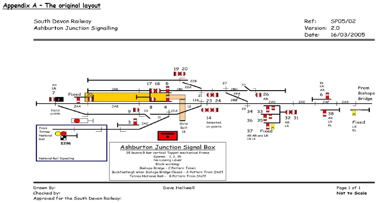
The South Devon Railway is in the process of building a "new" signalbox at Totnes Littlehempston known as Ashburton Junction after the original 'box removed in the early 1900's when control of the Ashburton Branch was moved into the Totnes 'box on the up main platform.
Below are three proposed track layouts for the new 'box with Layout "C" being the one most likely to be implemented.
Until the HMRI have approved the layout and locking nothing is finalised so these layouts are "for information only".
They do demonstrate how the signalling for a fairly simple station layout develops once the various engineering departments get together to discus a proposal.
 |
 |
 |
Introduction
Following expansion of the railway, it has been identified that an additional signal box is now required at Ashburton Junction to control the layout at Totnes Riverside. There have already been several meetings between the Signaling department and the Operations and Management to discuss the layout, and the last agreed layout was as per Appendix A.
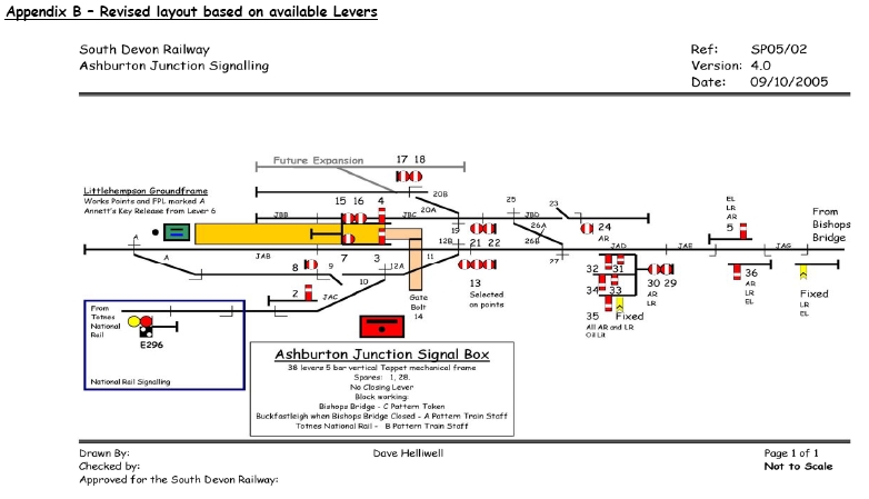
Following the fitting out of the Signal Box it was identified that there were only 36 levers available instead of the anticipated 38, so a revised layout is shown as Appendix B. There is a minor alteration to the south end with the addition of a ground frame instead of the hand point and fixed signals to control the points which has been able to free up some additional levers. The additional future siding on the western side of the layout was not included on the original plan, but was discussed at a site meeting held in April of this year. The basic signaled layout in Appendix B however remains as per the last meeting between all departments.
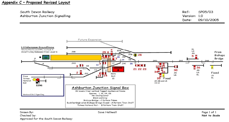
As the provision of a new signal box will be classed as major works by the HMRI there are several stages to go through with the paperwork. A meeting was held recently between the Permanent Way and Signalling Departments to discuss the finer points of the outline proposal to get the paper completed so that we can get an outline agreement in principle from the HMRI prior to the main application. At this meeting a revised layout was tabled and as a result of this another discussion is now required between all departments. The revised layout is included as Appendix C.
The layouts shewn in Appendix B and C are discussed below giving the advantages and disadvantages of the proposals. Any measurements given are approximate and subject to a detailed survey.
The purpose of this paper is to assist the management and operations departments in understanding the changes proposed and to allow questions to be formulated prior to any meeting that may be required to discuss the proposals. It is also to help in the reduction of any abortive work by the Engineering Departments.
The Proposal - Appendix B
The main change from the original layout, apart from the renumbering,
is to shew a ground frame to control the points at the southern end of
the layout. This has considerable advantages over the original proposal
of hand points and fixed signals:
- The Fireman / Guard would still need to get off and work the points irrespective of how they were to be operated.
- There were insufficient levers available to work the points from the signal box.
- It frees up more space on the locking frame albeit by one lever.
- The inner home signals would have the same meaning when a train is signaled into the platform - that is the line is clear to the stop blocks.
- It gets round the problem of restricted sighting of the shunt signal below the fixed arm, particularly at night.
- It allows passenger trains to be able to shunt completely up to the stop blocks in the event of long trains being worked in to the station without worrying about the clipping of points.
- The equipment required to achieve this is already available within the Signalling department
- without any additional cost on materials.
- The additional merits of the layout are discussed on the below.
Advantages
- Trains can arrive in all of the sidings and platforms direct from Bishops Bridge.
- Trains arriving on the western side can be quickly shunted out of the way into the head shunt.
- Trains can depart from any siding direct to Bishops Bridge.
Disadvantages
- Space on the locking frame extremely tight - just two spare levers
- Additional locking trays required as there is a lot of complicated interlocking
- Siding space is minimal, especially if the future expansion of the western side is carried out.
- Bay limited to 220 feet, Siding No 1 limited to 120 feet, Siding No 2 / back shunt limited to 70 feet, Head shunt off Siding No 2 135 feet long, and the head shunt next to main line limited to 135 feet. This would give a useable space of 680 feet
- Head shunt from siding No 2 would need several shunts to able to maximize its use.
- Signaller will need to be involved with most of the shunting which could lead to distraction from acceptance of trains and control of level crossings.
The Proposal - Appendix C
The significant change to the layout is the access to the western
side sidings. It was felt that there is a lot of space wasted considering
the ever increasing amount of rolling stock that is arriving on the railway.
The main change is that access to the sidings will now be from the head
shunt rather than the bay. There may be a minor amount of earth works required
to achieve this but it is felt nothing significant will be required.
The positions of the main line shunting signals have been moved.
It was felt that it would make shunting more flexible, with trains having
to travel less distance before setting back.
Advantages
- Less levers used leading to less complicated locking.
- Reduction of double ended points and FPL's making the layout more reliable and reducing the maintenance required.
- Reduction of the number of track circuits and insulated joints required.
- Avoids the problems of the restricted clearances on the platform from the new signal structure.
- Easier working of the triple disc - no reliance on complicated wiring run to select the appropriate disc.
- Increased siding space. The Bay would be 320 foot long, Siding No 1 would be 220 foot long, Siding No 2 would be 170 foot long, head shunt from siding No 2 would be 100 foot long, and Head shunt next to main line would be 320 foot long. This would give a useable siding space of 1130 feet.
- Allows for greater interest with train movements for special events - shunting in the sidings while still running trains into and out of the bay without hindrance.
- Less reliance on the Signaller for shunting.
- Trains can be formed up in the sidings prior to being shunted into the bay line for departure to
Bishops Bridge.
- Removal of the catch points from the sidings reducing the risk of accidental derailment.
- Cheaper to implement - Cost Saving.
Disadvantages
- Unable to access the sidings directly from Bishops Bridge - will require a double shunt.
- More reliance on the discipline of locomotive crews.
- Competent "shunters" required to control any shunting in the sidings and headshunts.
Next Steps
If there are no objections to the proposed layout detailed in Appendix
C, then a detailed PW survey will be required to confirm the final layout.
This will then allow the project specification to be completed and forwarded
to the HMRI to obtain the agreement in principle. To assist with this process
we will need to draft out changes to the safety case, operating instructions
and rule book to include in the project specification.
Due to the timescales involved with getting approval for a scheme
of this size an early agreement will be necessary. It is envisaged that
Bishops Bridge will be completed fully before any works are started at
Ashburton Junction. The possible implementation timescales for this project
will be late 2007 or early 2008 dependant on how early we can reach an
agreement.
Dave Helliwell
October 2005
 © South Devon Railway Trust 2005-9 |  |