Each section has two operational ’boxes and so can have trains moving in the same direction, one after the other, once the first has safely arrived into the protection of the second signal box.
It is possible to “switch out” Bishop’s Bridge Signal Box thereby joining the two sections together to make one section.
At the Totnes end is the National Rail network connection and trains are accepted and presented from/to this by the Ashburton Signal Box.
Ever wondered how a signalman remembers which levers to pull to put a train into the correct place and why they don't go wrong (normally) ?
Well it’s down to good training and a basic function called interlocking where the selection of one signal or point movement prevents an opposing move from being selected.
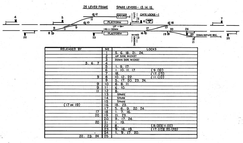 |
Above is a simple track layout with the points and signals marked on it and a table of what the levers do together with a list of which levers have to be moved before the chosen lever can be moved.
The role of a Signalbox is very important since it can affect the safety of the public and the trains. For this reason all efforts are put into training the Signalman to do the job correctly the first time but just in case he gets distracted then the signal frame will have been set up to prevent dangerous options being selected.
Over the main signal frame is a map, similar to the one above, of the section of track which the signalbox controls and any instruments that help the Signalman with his job. The most basic are the bells for the signalboxes on each side of him. Others are repeaters for signals he cannot see so he knows that they're displaying the correct aspect (red or green for a stop signal (yellow or green for a distant)).
There are a number of locking styles used to restrict the movement of signal and point levers but the Great Western Railway tended towards the tappet type as illustrated below.
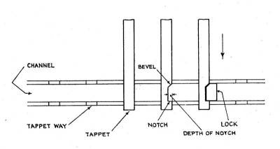 |
| General arrangement of tappet locking |
|
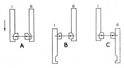
| In A either lever 1 or lever 6 can be moved.
In B lever 1 is moved so tappet blocks stop lever 6 moving In C lever 6 is moved so tappet blocks stop lever 1 moving |
In the example above the signalman cannot allow a train through the station until the road crossing gates have been closed and locked by moving lever 1. The pedestrian wicket gates are left until nearer the time and are locked when necessary by 2 and 3. With the road crossing made safe then the stop signals 5 & 6 and or 24 can be set to "Off" Obviously to release the "UP Main Outer Home" signal (5) the "West Crossover" controlled by lever 9 has to be in the straight through position so lever 9 can stop lever 5 being moved if this is not the case. The same is true for the "East Crossover" lever 17.
If you study the diagram above and the "locked by" table you can see how the setting of points to achieve a move is either prevented by the frame locking from achieving a potential conflict or, if their movement is allowed, they then lock other levers to stop new potential hazards.
The above is based on a 1956 decription of signal locking from a series of lectures for the Institution of Railway Signalling Engineers and wouldn't comply with modern requirements; particularly the pedestrian wicket gates.
| Typical Signal Lever Labels (or Plates) for the diagram above
© The Institution of Railway Signalling Engineers 1956 | ||||
|
1
Gate Locks Locked ________ Unlocked |
2
Wicket Locks Up Side Unlocked _________ Locked |
3
Wicket Locks Down Side Unlocked ________ Locked |
4
Up Main Distant 7. 6. 5. |
5
Up Main Outer Home |
|
6
Up Main Inner Home |
7
Up Main Starter |
8
Down Main To Goods Shed 9. 11. ________ Up Main 9. |
9
Main Crossover (West) |
10
Up Main To Down Main 9. |
|
11
Goods Shed ____________ Down Main 9. |
12
Goods Shed To Down Main 9. 11. |
13
|
14
|
15
|
|
16
Down Main to Up Main 17. _________ Down Refuge Siding 20. 19. |
17
Main Crossover (East) |
18
Up Main To Down Main 17. |
19
Down Main To Down Refuge Siding 20. |
20
Down Main ___________ Down Refuge Siding |
|
21
Down Refuge Siding To Down Main 20. |
22
Down Main Starter |
23
Down Main Inner Home |
24
Down Main Outer Home |
25
Down Main Distant 22. 23. 24. |
A signalman never acts alone in the sense that he always
has to ask the next signalbox along the line if he could send a train into
the next section before he allows it out of his section of control.
Obviously he needs to accept trains from the preceding section if
it is safe to do so.
To aid rapid confirmation of the expected action all
levers in a signalbox are painted in a distinctive colour which reflects
their purpose as detailed in the table below:
| Signal Box Lever Colours | ||
| Lever | Great Western Railway | BR(W) if different |
| Stop Signal | Red | Red |
| Distant Signal | Yellow (were Green when distant signals were red. Changed in late 1920's early 1930's) | Yellow |
| Point | Black | Black |
| Facing Point Lock (FPL) | Blue | Blue |
| Combined point & FPL
Point motor with FPL |
Blue over Black | |
| Electric Releases | Blue over Brown | |
| Mechanical locks
for wicket gates etc. |
Blue | Brown |
| King | Brown with white stripes | |
| Fog Signal
(aka Dets or Shots) |
Black with White Diagonals
(pointing up for UP Main and down for DOWN Main) |
Black with White Chevrons
(pointing up for UP Main and down for DOWN Main) |
| Spare (Unused) | White (Note: if lever still used to maintain locking lower 50% still coloured as per original use) | |
| Acceptance | Half Red half Brown | |
| Notes:
|
Signals released electrically by another box e.g. Line
Clear had a white stripe half way down.
Goods line signals had a broad Black band half way down and if released by Line Clear the smaller white stripe would be in the centre of this. Relief line signals had the lower half painted Black so stop levers were half Red half Black whilst distants were half Yellow half Black. If a white stripe was required this divided the two colours. For Intermediate Block signals Red over Yellow with a white stripe for the release. Top of lever shortened if motorised to remind signalman of lack of weight behind lever. |
|
Further information can be found at www.signalbox.org or The Institution of Railway Signalling Engineers
 © South Devon Railway 2002-18 |  |