"Vacuum Brakes"
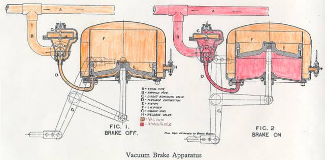
This is a GWR Diagram of the braking system and shews the two conditions
of "Brake Off" and "Brake On" - it's been coloured for clarity. The clever part is that both these conditions are achieved with one continuous pipe (the "Train Pipe" "A" running the length of the train. At the start of the journey the Driver "Blows" the brakes off by using a steam powered ejector to create the vacuum (coloured orange) in the train pipe (A) which causes the brake cylinder piston (E) to fall to the bottom of the cylinder (F). The continued evacuation reduces the pressure in the top of the cylinder until it reaches that of the train pipe and so the piston is in balance, but the brakes remain off due to gravity.
When the pressure in the Train Pipe (A) rises (coloured red) due to the Driver applying the brake (or one of the safety features activating) the piston (E) is forced upwards due to the imbalance in forces acting on it. The vacuum above the piston is maintained by the one way valve effect of the rubber piston ring. The rising piston pulls on the brake rigging (G) and therefore pulls the brake shoes into contact with the wheels generating a frictional drag on them which converts the momentum of the train into heat which slows the train down. In order to provide smooth and progressive braking there is a "Direct Admission Valve" (C), which has a diaphragm in it which responds to the imbalance in pressures like the brake cylinder piston and helps to destroy the vacuum locally. The advantage of doing this is that all vehicles in the train start braking earlier than would happen otherwise since the all air doesn't have to enter the Train Pipe via the Driver's brake control.
The release valve (H) is to let air into the cylinder above the piston and
therefore release the brake without the need to create a vacuum in the train pipe. This is usually done for shunting, but can be used where locomotives
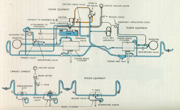
from different regions/companies are used. The GWR favoured a vacuum capable of lifting 26 inches of mercury whereas the other railways (and BR diesels) use 21 inches. The main reason behind the difference is that the greater the pressure difference the more force that is available, but maintaining the higher vacuum costs steam. The GWR solved this with a mechanical pump (the spitting you hear when the locomotive is shunted) whereas the other railway companies used a large ejector to release the brake and a small one to maintain it; hence costing steam. If a 21 inch locomotive is coupled to a train in place of a 26 inch locomotive it won't be able to release the brakes and so the vacuum above the pistons needs to be reduced manually - this is called "Pulling the Strings"
|
| Diagram of vacuum brake as used by GWR Locomotives and Rolling Stock |
 © South Devon Railway Trust 2002-9 |  |